Analog DC Motor Position Controller
I was recently talking to group of high school students from the York School I mentored in their rookie season of First Robotics. Before I go any further, if you haven't seen First Robotics in action take a look at their website. It will re-inspire you about the talent of the next generation of American engineers.
Our design this year required a scoop, similar to the set of forks on a forklift, to scoop up a 24in diameter yoga ball and load it into our catapult for scoring or passing.
My team hadn't worked much with position feedback systems, given that it was their rookie season, so I decided to build a demonstrator to show the basic concepts of analog feedback control. From this analog demo I plan to extend the concepts to digital control with feedback. Then we can apply this knowledge to robot designs in the future.
The design is built from the schematic I drew below with motors/pulleys/shafts/etc from the Actobotics line at Sparkfun.com. By the way, I've grown to like the digi-key online schematic tool Scheme-it available here. Design details are provided below. I'll probably add some video and photos of the working system here soon.
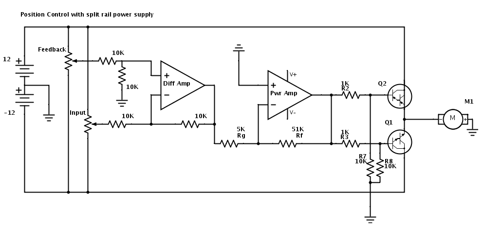
The Design - This design allows a user to rotate a knob at the input potentiometer and then the motor will rotate to the matching angle before decelerating to hold the ordered position. The schematic is best described in functional parts identified from left to right:
- +/- 12 Volt, split rail power supply
- Input and feedback potentiometers
- Differential op-amp
- Proportional op-amp
- PNP and NPN Darlington transistors to control power delivery to the motor
- 12 Volt DC gear motor
12V Split Rail Power Supply - Fundamentally if we want to move a motor in both directions then we need a way to make electricity run through it in both directions. There are reallly two ways to do this:
- Install the motor in the middle of an H bridge which is described for beginners elsewhere on the web. If you are looking to implement an H bridge or want to learn more about it this is my favorite link on the subject here.
- Power the motor from a supply that includes both positive and negative terminals.
Because there is so much info on H-bridges I wanted to implement a different solution so that there is a hobbyist tutorial on the web for it that I couldn't find as I began this project. Therefore, I'm using the second option here. Note that the ground reference for the circuit is BETWEEN two 12 volt power supplies. Therefore, if you measure from ground in the downward direction you are at -12 volts on the bottom terminal, and if you measure from ground in the upward direction you are at +12 volts on the top terminal.
From this setup if we flow power from the top supply into the motor it will run in one direction and vice versa if we power it from the bottom supply
Input and Output Pots - There is nothing special about these pots. In fact they don't even require a matching resistance value (I'm using a 10K and 50K pot). However, your physical system will be limited to the number of turns the pot can make. Fundamentally, when you turn the dial on the input pot you are setting a reference voltage. Then the feedback pot from the physical system represents the location angle of machine you are trying to control.
Differential Op-amp - The circuit shows two op-amps, but I'm just using a single TL082CP chip that has two op-amps on the same IC. Not shown is that the op-amps are both connected to the top and bottom power rails on their respective Vcc+ and Vcc- inputs. I'm going to give a VERY brief overview of how I'm implementing op-amps for this design. My preferred introductory resource for op-amp design is here.
You will notice that the first op-amp is surrounded by four 10K resistors. These resistors set up a relationship so that the voltage coming out of the op-amp and flowing into Rg is equal to (Vfeedback - Vinput). Thus the only voltage that gets passed along for amplification represents the differnce between the two positions.
Power Amp - The differential signal enters the power amp network through Rgain (Rg) and is amplified accourding to gain equation for an inverting op-amp, Vout = -Vin(Rf/Rg). Thus for this circuit we have a gain of about -10 (i.e. 51K/10K).
We use the "inverting" op-amp because it gives a simpler expression for gain. The non-inverting formula is Vout = 1 + Vin(Rf/Rg). The "1+" component of this formula gives output voltages that aren't centered around 0. For example if the difference signal is -.1V, then the non-inverting amplifier equation would reduce to 0 = 1 + (-.1)(51K/5K). This would result in no control voltage to the motor even though there is a difference signal coming out of the differential op-amp. That's bad...when there is a difference between the input and feedback voltages WE WANT A CONTROL SIGNAL to move the motor to erase the difference.
So going back to our inverting op-amp design, if we have a voltage difference of .5V coming into the power amp network, then Vout will be about -5V, based on a gain of about -10. But what if the inversion from a positive difference signal and a negative amplified voltage causes the motor to run in the wrong direction?
Good question..easy fix. Just swap where the motor wires are plugged in. By swapping the wires the motor will reverse direction and line up to the intuitive direction you want it to turn based off your input knob's rotation.
Darlington Power Transistors - Once the motor control voltage comes out of the power amp we use a network of four resistors and two transistors to control how that voltage flows into the motor. I used TIP 102(NPN) and TIP 107(PNP) Darlington Pair transistors. These workhorses can power up to 8 amps with cooling. So for lower amp uses like small DC motors they are almost indestructable. The interesting thing about the design is that only one transistor at a time will come on.
Negative voltage turns on the PNP transistor (Q2). So when the signal coming out of the amp is negative, Q2 turns on and allows current to flow from the +12V supply through the transistor then out to the motor and back to ground.
Similarly, positive voltage turns on the NPN transistor (Q1). So when the signal coming out of the amp is positive and flows into the base of the NPN transistor it opens the gate to allow -12V to flow through the transistor, out to the motor and up to ground.
There will always be a dead zone between the two transistors where small voltages out of the power amp will not turn on either transistor. There are compensation techniques for this, but they require another round of analysis beyond this introductory tutorial.
Follow On Improvements - Every design can get better and there a few things about this design that could get better. Some of them include:
- This is a "proportional" controller because the motor control signal is proportional to the difference of the input and output voltages. The next level of sophistication would be to add "integral" control to the system. Integral control would allow those small differences in position error that aren't large enough to turn on the transistors to add up over time to get the motors moving and erase "error to a step input".
- The feedback potentiometer is limited by the number of turns it can make. I could replace the pot with a position encoder similar to the "Grey" code encoder described on this site to get a digital position indication for the feedback signal. This would allow more flexibility, but would require a digital microcontroller to oversee the control process.
- Finally, I'm looking forward to incorporating some position control feedback into a FIRST robot next year and teaching the students in our Monterey Bay area high schools how to use these ideas in their designs.