Motor Sink Circuit
I use this circuit all the time to control the flow of power to a motor from an Arduino or other microcontroller. I made a page for it so I have quick reference to it when I need it.
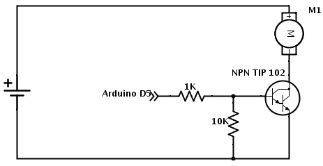
The Design - The 10K resister acts as a pulldown resistor to keep the base of the NPN transistor off when there is no signal present. When a +5 signal comes in on the input line it is biased through the the 1K resistor and turns the TIP 102 Darlington power transistor on. This allows power to flow from the power source through the motor.
Speed Control - A PWM signal on the input pin will serve to provide speed control of the motor if desired.
Limits - The TIP 102 can sink 8A of current with proper heat management. So this circuit is acceptable to run most DC hobby motors. The TIP 102 has two silicon BJT junctions that drop the output voltage .6V each. So set the source voltage about 1.2V above the max limit for the motor to run at full power.