Alfred
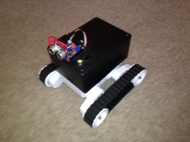
My sons and I have been working on a little robot named Alfred to run around the house autonomously. They've got grand plans to grow this little guy into something that can clean their room. Step-by-step I tell them.
This blog lays out the challenges we've faced, the components we've used, and the programming techniques we rely on to solve problems as we build this robot.
I've not included code on this site, but instead favored an approach that explains the ideas we put into place in our Arduino code. I might include snippets later, and will probably set up a repo if anyone is really interested in the full code base.
The basics
Microcontroller: Our microcontroller is the hub of this simple robot. For simplicity we chose the Arduino Uno R3.
Sensor: Parallax PING))) sensor mounted to a few pieces from Hayden's erector set and articulated on a Futaba S3004 servo.
Chassis: Rover5 with 4 motors and 4 encoders. I've disconnected the two rear motors for now because I'm using the stock treads and don't need the power (or headache) of balancing torque on each tread with two motors running per tread.
Motor Controller: I'm using the board recommended by Sparkfun that is made by the same manufacturer as the chassis.
Data Logger (Added 12 Aug 2013): Using the OpenLog from Sparkfun. Great tool; easy, and works as advertised.
Power
ORIGINAL SETUP - Power was the first thing we needed to get sorted out. We started out with a 9V Alkaline powering the Arduino board. The servo and ultrasonic sensor were powered from the 5V output pin on the Arduino board. Motor power was provided by 5 AA batteries in series for a nominal 7.5V, and the motor controller VCC was also powered off the Arduino board's 5V output pin.
In testing, each individual component worked fine with this power set up. We could run the servo/sensor combination, and seperately we could run the Rover5 around the living room.
BUT...when we hooked it all together this did not work! The power requirement on the Arduino 5V output pin was too large when it had to drive the servo, ultrasonic sensor, and the motor controller at the same time.
POWER SETUP 2 - In July 2013 we are running the messy setup in the picture below. The advantage is that it is working. The disadvantage is that it's a mess!
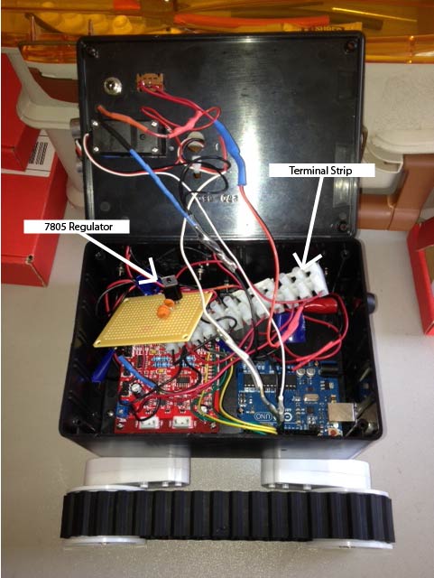 I've still got a 9V alkaline powering the Arduino, but we've taken our 5 AA cell battery and run a split from this into a 7805 linear voltage regulator to create a +5V output that runs to the terminal strip where I've connected the servo, ultrasonic sensor and Vcc for the motor controller. The unregulated 7.5V from the 5 cell battery is still powering VBatt on the motorcontroller. Although this is working the disadvantages I see are:
- The motors are killing the AA battery pack too quickly.
- I don't like having two battery sources (9V and 5 AA's).
- My 7805 regulator (Micro Electronics ML7805A) is only rated to about 1A. This is not enough to handle the motors under stall conditions plus the peripherals.
POWER SETUP 3 - My plan to address the deficiencies in power setup 2 are:
- Order a 2S 4000mAh LiPo battery to replace the 5 AA cells. This will give me lightweight, modular, rechargable power.
- Order a 5 Volt, 5 Amp Universal Battery Eliminator (UBEC). The UBEC will give me switched regulation down to 5V that can power up to 5 Amps worth of servos or peripherals. Additionally, the switched regulator is more efficient than the 7805 linear regulator.
- Design and build a low voltage cut-off circuit to protect the LiPo battery from over-discharging.
I've got this battery and this UBEC on order.
The work to build the Low Voltage Cutoff (LVC) circuit is proving to be an interesting challenge.
19 Aug - Discharging a LiPo battery below 3V per cell under load can damage the battery making it unable to accept full charge or hold voltage under load [see wikipedia].
The battery I've got on order is a 2 cell battery so we need it to cut it off no lower than 6V. For a margin of safety I'm going to have it cut off at 6.2 Volts.
The schematic below, found at electro-tech-online, is going to be my first attempt to build this circuit.
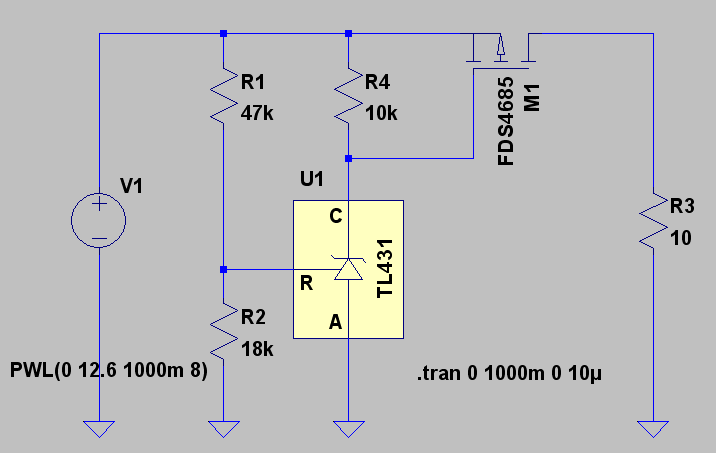
I like this circuit because it uses a MOSFET to control the power flow, so there should be no problem with me putting several amps through the circuit. The resistor values here are set up to cut an 11.1V (3 cell) LiPo off at 9V...so I'll need to make some changes. Also, I couldn't source the MOSFET part number in the circuit so I found this IRF9520 from Jameco. I also sourced the TL431 programmable precision voltage reference from Jameco.
This is my first project with MOSFETs so I just wanted to make sure I understood how to turn the channel on an off. I watched this video from Pete. Then I built this test circtuit and you can see the LED glowing brightly with the switch in the "on" position from the diagram. My 9520 MOSFET is a P-Channel device which means the power channel conducts electricity when the gate is tied low so in the "on" position in the circuit the gate is tied low through the 10K Ohm resistor and the channel opens up to allow flow around the circuit to light the LED.

Next I needed to get familiar with the TL431. According to the datasheet the TL431 has, "active output circuitry which provides a very sharp turn-on characteristic, making these devices excellent replacements for Zener diodes in many applications, such as ... power supplies."
After spending a few hours looking at the ouput from the TL431 and building a few spreadsheets to understand how to set Vout, it is apparent that I'm going to need to spend a few more hours before I feel confident designing with this component.
Aug 23 - I've read a lot more to try and understand what I'm doing. These resources are helpful:
- Texas Instrument Application Note on Shunt Regulators
- Lesson on Zener Diode Shunt Regulators
- Page on RC LiPo batteries
- TL431 Adjustable Shunt Regulator datasheet
- Linear Technology Application Note on Voltage References
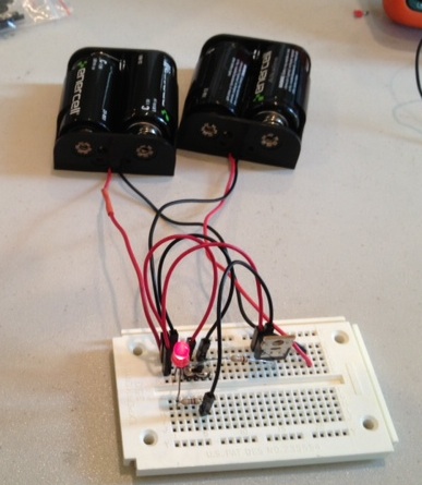
With this new foundation I was able to look at my setup with fresh set of eyes, and I'm happy to post the success photos below.
The breadboard on the left is my new power supply. Yeah...I know...I should put it in an enclosure, and I'm sure I'll do that soon enough.
The breadboard on the right is my low voltage cut-off circuit. The two big potentiometers between the breadboards set R1 and R2 from the schematic above.
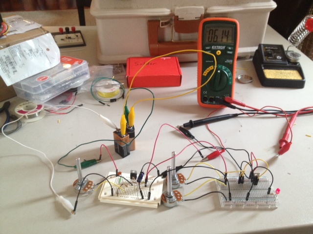
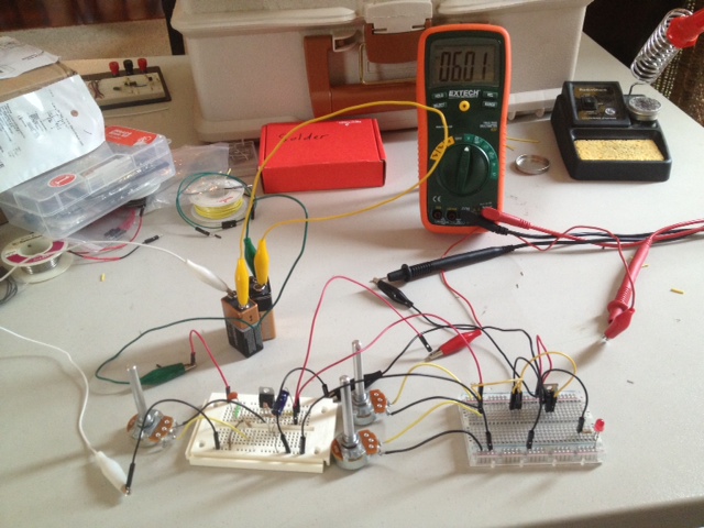
In the left photo notice that the LED in the bottm right of the picture is burning brightly at an input Voltage on the multimeter just above 6V. Then in the photo on the right the LED is off with Voltage right at 6V. The LED simulates the load being shut off when voltage drops below 6V.
However, I'm not real happy with the solution yet. The LED fades on and fades off between a range of about .1V. This is not the crisp cut-off I want. If the power is "browned" out over the course of .1V then it could damage the electronics in the robot.
It's time to get ready to coach football practice. So I'm going to leave it here for the day.
 4 Sep - My work a few weeks ago was a quick hack. Before I solder anything and risk my LiPo battery pack I need to do the stubby pencil work and complete an analysis of this circuit includong current requirements for all the components.
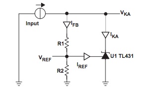
We are trying to solve for the values of R1, R2 and R4 from the grey schematic above.
R4 limits the current flowing into the TL431 across all battery voltages and when the battery voltage falls too low to reverse bias the TL431, then R4 acts like a pull-up resistor on the MOSFET gate, effectively shutting down current flow. My design goal for current flowing through the TL431 (IKA) is 3mA. Solving the equation when the battery is at minimal voltage we get:
- V = IR
- 6.1 = .003 * R
- R = 2033 Ohms
The closest resistor value I've got to this is 2.2K, so we are going to set R4 to 2.2 Ohms, which limits IKA to 2.8mA...a little less than design, but still well above the minimum of requirement of 1mA.
Next, the TI application note linked above has a good discussion of how to calculate the proper current, resistor and power requirements for this circuit. I'm using these formulas and the image at the beginning of this paragraph. Nominal values and other datasheet values are taken from the datasheet linked above.
- R1 = (VKA – VREF) / IFB
- R2 = VREF / (IFB – IREF)
- Vref = Vnom + (Ika-Inom)*Zka + (Vka-Vnom)*-.0014
My design goals are:
- VKA = 6.1V
- Cathode current (IKA) = 3mA
- Feedback current (IFB) = .2mA
Solving:
- VREF = 2.495 + (.003-.010) * .2 + (6.1-10) * -.0014 = 2.499V
- R1 = 18,057 Ohms
- R2 = 12,568 Ohms
I don't have precision resistors for R1 and R2 so I use a 5% tolerance 10K resistor in series with a 10K 15-turn pot ($2.99) from Radio Shack to dial up the resistor values for R1 and R2.
To see all the design goals, datasheet parameters, and solved values click here.
With the TL431 tuned to the values above and functioning as a 6.1V Zener diode I should be able to control the gate of the P-channel MOSFET.
The P-Channel MOSFET is turned "on" when voltage is low. Therefore, whenever the TL431 is letting current flow at battery voltages greater than 6.1V, the MOSFET gate is connected to ground through the reverse biased TL431. When battery voltage drops below 6.1 Volts the TL431 looks like an "open" switch, current stops flowing to ground and the MOSFET gate is tied to to Vbatt through the pull-up resistor R4. With the MOSFET gate tied to Vbatt the MOSFET will cut-off and prevent the batteries from draining down any further. The last thing to do is take a close look at the datasheet here to make sure I am using the right pins on the TO-220 package.
Success! The turn on is sharp and right at 6.1V where I wanted it. Much improved over my 22 August version where the cut on/off was too gradual over a .1V range. With the TL431 tuned the cut-off is clear and distinct on the workbench. Now I need to test it with the battery.
5 Sep - My test plan from here will be:
- Connect up a 5 cell battery (7.5V) of alkaline batteries and add a few power resistors to create a resistive load to drain the batteries. I should see the circuit cut off power when the alkaline cells get down to 6.1V. (Successfully completed 5 Sep)
- If I get a successful test from step one then I'll rig up my LiPo battery and run the same test.
I set this test up on 5 Sep, with two 10 Ohm resistors in parallel as the load. The theoretical power should have been about 1.5A, but when I plugged up my multi-meter the circuit was only pulling about 1.1A.
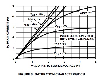 Looking at the datasheet for the 9520 MOSFET, I can see the problem in the saturation curve to the right. My Vgs is a little above -5V. Looking at the -5V curve shows that the drain current shuts down a little above 1A.
I'm going to have to change the circuit to fix this. I guess I've got two choices. First, I could run a higher voltage battery so the Vgs is larger. For example, if I ran a 3S LiPo battery at a nominal 11.1V then Vgs should approach -7V so I could easily push 3 or 4 Amps. My second choice would be to look for a different MOSFET that can run more power at the -5V Vgs I've got with the 2S battery.
Another little problem now that I'm running at full power loads is that the MOSFET is running too hot. My multi-meter also has a temperature sensor on it, so I took a reading on the MOSFET, and it was running at 110 degrees C. I do not have a heat sink attached to the MOSFET so I'm going to need to add that right away.
On a positive note, while I was typing these notes, the drain down experiment continued on my workbench and it shut off the LiPo precisely at 6.1V. So the low voltage cutoff circuit was a success. However, as I explained above, I've got some bugs to work out before I solder up a verson to go in Alfred.
6 Sep - Not much activity today except that I ordered another MOSFET that should deliver more power with -5Vgs. I spent some time shopping the Jameco catelog last night and realized that if I want to get more than about 4A then I will need to raise the voltage of the power source, but until then I should be able to get a solid 3A from a 2S LiPo battery with a MOSFET designed to provide an open channel my gate to source voltage level. I had to get a few other items from Sparkfun, so I also ordered the P-Channel MOSFET they sell here.
22 Nov - I got to California for my new job about six weeks ago and broke out Alfred for the first time since I arrived. It took me a while to get back up to speed on my work, but I was able to recreate my last power management board and found a few problems.
- The cutoff on this device is not crisp. The LED browns out as the voltage drops toward 6.2
- The original values I chose for R1 and R2 to provide a reference voltage were not good choices. I've learned that the precision voltage reference (TL431) is a really cool component in the way it will hold a constant voltage reference while input voltage to thie circuit is changing dramatically. However, I've also learned that Vref MUST be about 2.5V less than Vbatt(min) in order for the TL431 to give a good reference indiction.
- I wrote a quick Matlab script to calculate resistor values for these TL431 devices (Matlab 'm' file...can be opened in notepad).
- I had to add a comparator after the voltage reference now because I dropped the ref volage down to 3.5 volts. This reference voltage gets compared to a voltage divider across the two power rails and the comparator inverts its output to drive the MOSFET. This part is working great, but there is still a mess of feedback problems right before the transition. I'm pretty sure this can be fixed with hysteresis, which is explained in detail here.
Object Avoidance
July 2013 - The first attribute we wanted to install in this robot is autonomous object avoidance. We've gone after this by using the servo to rotate the distance sensor through 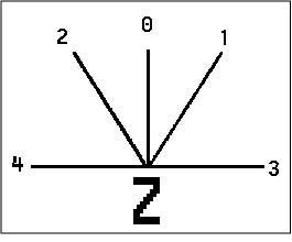 a series of test points. As of Aug 2013 we are using five test points laid out as shown int the diagram to the left. At each test point we take a distance measurement and then compare this measurement against a "trip point". If the distance to the nearest object is inside the trip point then we record that in a bit set.
The bit set is called "sensor_bits" in the code. Each bit represents the latest measurement for its corresponding test point. So B00000, would mean that all bits are clear. Whereas, B00100 would indicate that the center sensor was "tripped" because the range finder detected an object inside the "trip distance" for that sensor.
Then on each loop the microcontroller looks at sensor_bits and creates a motor control vector that it drives the tracks.
August 2013 - The control logic described above works for any object detected by the sensors. However, in the picture to the right you can see that obstructions below the sensor height of six inches are not seen by the rangefinder. Therefore, the robot runs into the bar on this table in our living room and gets stuck.
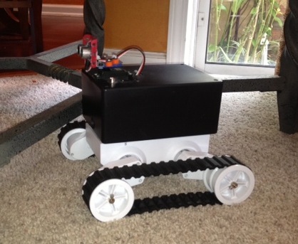
To fix this I'm going to take advantage of the current sensing provided on the motor controller. A motor current spikes when it is stalled out, and I'm hoping that the bump into the table or other object not detected by the rangefinder will create a motor current spike that we can sense and use to add a new behavior to Alfred.
I've added a data logger to help solve this because I need to take some readings on what the steady state current is when the robot is working and what the value of the spike is so I can set a threshold for the "bump".
Based off today's test (11 Aug, 2013) with a 7.5V Alkaline battery pack, it appears that the stall current is about 1A.