"Grey" Code
In October of 2013, Greyson heard about Gray Codes named after Frank Gray and explained here. Since we call him "Grey" he thought it would be cool to understand Gray Codes. This project is an absolute position encoder that allows Greyson to compare why Gray Codes are a more effective way to encode some information than straight binary encoding.
The Basics
Power: We just need reliable 5V DC power to drive the sensors, display and processing chips in this circtuit. So we used a standard 7805 linear voltage regulator (Micro Electronics ML7805A) with decoupling capacitors.
Microcontroller: There is no microcontroller in this project. I wanted to build the electronics for this one to make a direct Analog to Digital conversion of the disk signal for each bit and then send these bits down one of two paths:
- For bits read from the binary coded disk they will be sent directly to the BCD to 7-segment LED driver.
- For bits read from the Gray coded disk they will be sent into a quad 2-input XOR chip and converted to BCD and then routed to the 7-segment LED driver.
Sensor: We are using the QRE1113 line sensor breakout from Sparkfun to read the disk. This sensor has an IR LED and an IR receiver. A white surface will reflect the IR light and a black surface will absord the light. The sensor sends this change as an anolog signal on the output pin. After watching the sensor response on the oscilliscope it looked 2.68 volts was a good threshold.
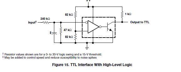
Analog to Digital Conversion: We are using a separate comparator for each bit, and I've chosen then Texas Instruments LM311 chip for this function. The datasheet for this component is thick with lots of application examples. It took a little while to find the right application circuit, but this one closely resembled what we were trying to do. I changed the resistor divider values to better match the input performance of our sensor, but the overall configuration worked in our circuit.
An important point for beginners in electronics is that the LM311 is an open collector device and the 1K pullup-resistor is REQUIRED to make this device function the way we want it to. Learn more about why many ICs are open collector here, especially the paragraph called "function".
As noted, in the paragraph about the sensor we wanted to set the comparator threshold to 2.68 volts so we set the voltage divider on the comparator's Vref input to get this result.
Gray Code to BCD Conversion: Gray Code can be converted into BCD by an XOR algorithm. Decent explanation of the conversion here, but I may write another explanation to make it clearer. I used a Texas Instruments 7486N from Jameco to provide the necessary XOR gates. Datasheet.
Display Logic: I found a great little IC called a 7447N that has four logical input bits and converts the BCD input into the A-G output to drive a common annode 7-segment LED. Finding this chip made this project possible without having to write code for a small microcontroller to run the display.
Display: I grabbed this little 7-segment LED display from Sparkfun, and the cool blue color is different enough to make the display just a little unique. Datasheet.
Note on Wiring Colors: While building this project I tried to pay attention to wiring colors so that Greyson could learn and explain what signal or data is flowing down the different color wires. As best possible I adhered to the following scheme:
- Red - Vcc (+5V)
- Black - Ground
- Grey - Gray Code Logic after XOR conversion
- White - Disk signal after ADC
- Green - User selected logic signal & Display driver signal
- Yellow - Analog voltages
The Cool Stuff
Code Disks: The electronics for this project were pretty simple and straightforward. The really neat part is watching Greyson learn about binary and Gray code. So I built the sensor system and I think he understands the functional description of the pieces, but he built the code disks all by himself. He wanted to test whether a binarcy coded disk or a Gray coded disk performed better for an absolute position encoder.